Shaders’ Outpost
Moderators: another_commander, winston

-
JensAyton

- Grand Admiral Emeritus

- Posts: 6657
- Joined: Sat Apr 02, 2005 2:43 pm
- Location: Sweden
- Contact:
Well, I now have tangent generation almost working. The one slight flaw is that it generates the wrong tangents, but in apparently consistent ways. This should be an easy fix… tomorrow some part of today which is daytime. Overall, tangent generation was a simple enough change I can hardly believe it took me this long to get around to implementing it. I might even sneak it into 1.72.1. :-)
E-mail: [email protected]
-
Griff

- Oolite 2 Art Director

- Posts: 2510
- Joined: Fri Jul 14, 2006 12:29 pm
- Location: Probably hugging his Air Fryer
Wow, that's really, really amazing!
I don't know much about creating normal maps, but it looks like nvidia have some sort of texture tool here http://developer.nvidia.com/object/nv_t ... tools.html that will create a normal map from a texture image - there looks like there's a plugin for Gimp too! cool, i thought you needed something like zbrush to make normal maps so having free tools available is great!
Can't wait to see oolite normal mapped asteroids!
-
JensAyton
- Grand Admiral Emeritus
- Posts: 6657
- Joined: Sat Apr 02, 2005 2:43 pm
- Location: Sweden
- Contact:
Starting in 1.73, there will be a new default vertex shader, oolite-tangent-space-vertex.vertex. oolite-standard-vertex.vertex will be kept around for compatibility, although I don’t think anyone except me used it in OXPs. The fragment shader default fragment shader has of course also been updated.
From a user perspective, the main new feature of these shaders is the normal and parallax mapping, but those only add up to four lines of code. From a shader-hacking perspective, the main change is that everything is done in tangent space instead of mixed world space and model space.
Warning: if you happen to know the formal mathematical definitions of “tangent space” and “binormal”, note that these terms are abused a bit in graphics. “Normal” is used sensibly and the “tangent vector” is a vector in the actual tangent space of a surface, though.
Tangent space is a coordinate basis using vectors based on the surface of an object and its texture map. In particular, the basis vectors are called tangent, binormal and normal. Normal is the, er, normal normal, that is, a vector pointing straight out from the object (and defining what “straight out” means). Tangent is defined in terms of the texture map. This is slightly tricky to explain without a diagram, but it’s the vector from texture coordinate (0, 0) to texture coordinate (1, 0), projected onto the plane perpendicular to the normal (i.e. the tangent plane) and normalized. The binormal is the cross product of the normal and tangent, i.e. a vector that’s perpendicular to both. The normal is specified in the DAT file, and the tangent is calculated by Oolite (at least in the trunk), and the binormal is calculated in the vertex shader:
The first line declares an attribute variable, which we haven’t seen before in Oolite-related shaders. This is a variable which has a value set for each vertex by the host (i.e. Oolite), unlike a uniform where the host sets a value that applies to the whole model.
The last line builds a transformation matrix from model space to tangent space. This is then used to convert the various vectors we’re interested in:
The new vertex shader also sticks the texture coordinate into a varying vector instead of extracting it in the fragment shader (I’m not sure whether this makes a difference either way for performance, but it simplifies the fragment shader slightly, which is good) and projects the vertex onto the screen:
Over in the fragment shader, most things actually work exactly as before, since we’ve applied the same transformation to both the eye vector and the light vectors. However, if we’re not doing normal mapping we can make some simplifications because we now know that the normal will allways be (0, 0, 1). For instance, the expression dot(normal, lightVector) in the diffuse lighting calculation simplifies to lightVector.z.
The very simple, but very fast, parallax mapping method used in the default shader works like this:
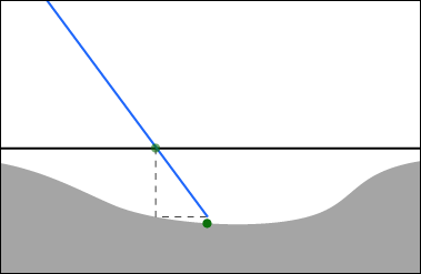
The parallax map is sampled where the eye vector hits the actual surface, and is used to project the eye vector onto the virtual surface defined by the parallax map. (The offset can be positive or negative.) The diagram accurately illustrates how imprecise this method is: the parallax value at the projected point is different from the one at the intersection pount, which is what’s actually being used. The shallower the viewing angle and the higher the parallax scale, the more wrong it gets, but this technique should be sufficient for stuff like hull plating. I’ll probably implement one of various more accurate (but slower) techniques that exist for high-quality mode. Google for “offset limiting” and “relief mapping” if you’re curious.
The updated shader also does away with the macros used for lighting before and uses functions instead:
There’s not much to say here, except that varying variables are now used for light vectors instead of gl_LightSource[idx].position.xyz because the light positions need to be transformed to tangent space in the vertex shader. The new shader also avoids normalizing the light vectors twice, which was a bit silly.
From a user perspective, the main new feature of these shaders is the normal and parallax mapping, but those only add up to four lines of code. From a shader-hacking perspective, the main change is that everything is done in tangent space instead of mixed world space and model space.
Warning: if you happen to know the formal mathematical definitions of “tangent space” and “binormal”, note that these terms are abused a bit in graphics. “Normal” is used sensibly and the “tangent vector” is a vector in the actual tangent space of a surface, though.
Tangent space is a coordinate basis using vectors based on the surface of an object and its texture map. In particular, the basis vectors are called tangent, binormal and normal. Normal is the, er, normal normal, that is, a vector pointing straight out from the object (and defining what “straight out” means). Tangent is defined in terms of the texture map. This is slightly tricky to explain without a diagram, but it’s the vector from texture coordinate (0, 0) to texture coordinate (1, 0), projected onto the plane perpendicular to the normal (i.e. the tangent plane) and normalized. The binormal is the cross product of the normal and tangent, i.e. a vector that’s perpendicular to both. The normal is specified in the DAT file, and the tangent is calculated by Oolite (at least in the trunk), and the binormal is calculated in the vertex shader:
Code: Select all
attribute vec3          tangent;  // Provided by Oolite
//...
void main(void)
{
    // Build tangent basis
    vec3 n = normalize(gl_NormalMatrix * gl_Normal);
    vec3 t = normalize(gl_NormalMatrix * tangent);
    vec3 b = cross(n, t);

    mat3 TBN = mat3(t, b, n);
The last line builds a transformation matrix from model space to tangent space. This is then used to convert the various vectors we’re interested in:
Code: Select all
    vec3 eyeVector = -vec3(gl_ModelViewMatrix * gl_Vertex);
    vEyeVector = eyeVector * TBN;

    vec3 light0Vector = gl_LightSource[0].position.xyz + eyeVector;
    vLight0Vector = light0Vector * TBN;

    vec3 light1Vector = gl_LightSource[1].position.xyz + eyeVector;
vLight1Vector = light1Vector * TBN;Code: Select all
    vTexCoord = gl_MultiTexCoord0.st;
gl_Position = gl_ModelViewProjectionMatrix * gl_Vertex;Additionally, the expression -reflect(lightVector, normal) simplifies to vec3(-lightVector.x, -lightVector.y, lightVector.z).Proof wrote:By definition, dot(u, v) is equivalent to u.x * v.x + u.y * v.y + u.z * v.z.
Given u = (0, 0, 1), we get v.x * 0 + v.y * 0 + v.z * 1 = v.z.
Since the surface normal is a constant, normal mapping is simply implemented by replacing it with a value from the normal map texture.Proof wrote:By definition, reflect(v, n) is eqivalent to v - 2.0 * dot(n, v) * n.
Given n = (0, 0, 1), we get:
v - 2.0 * v.z * (0, 0, 1) [see previous proof]
= v - (0, 0, 2.0 * v.z)
= (v.x, v.y, -v.z)
The negation is of course (-v.x, -v.y, v.z).
Code: Select all
#if OOSTD_NORMAL_MAP  // Defined to 1 by Oolite if a normal map is to be used
    vec3 normal = texture2D(uNormalMap, texCoord).rgb;
#else
    const vec3 normal = vec3(0.0, 0.0, 1.0);
#endif
The parallax map is sampled where the eye vector hits the actual surface, and is used to project the eye vector onto the virtual surface defined by the parallax map. (The offset can be positive or negative.) The diagram accurately illustrates how imprecise this method is: the parallax value at the projected point is different from the one at the intersection pount, which is what’s actually being used. The shallower the viewing angle and the higher the parallax scale, the more wrong it gets, but this technique should be sufficient for stuff like hull plating. I’ll probably implement one of various more accurate (but slower) techniques that exist for high-quality mode. Google for “offset limiting” and “relief mapping” if you’re curious.
Code: Select all
#if OOSTD_NORMAL_AND_PARALLAX_MAP
    float parallax = texture2D(uNormalMap, vTexCoord).a;
    parallax = parallax * uParallaxScale + uParallaxBias;
    vec2 texCoord = vTexCoord - parallax * eyeVector.xy * vec2(-1.0, 1.0);
#else
    #define texCoord vTexCoord
#endifCode: Select all
vec4 CalcDiffuseLight(in vec3 lightVector, in vec3 normal, in vec4 lightColor)
{
#if OOSTD_NORMAL_MAP
    float intensity = dot(normal, lightVector);
#else
    float intensity = lightVector.z;
#endif
    intensity = max(intensity, 0.0);
    return lightColor * intensity;
}


vec4 CalcSpecularLight(in vec3 lightVector, in vec3 eyeVector, in float exponent, in vec3 normal, in vec4 lightColor)
{
#if OOSTD_NORMAL_MAP
    vec3 reflection = -reflect(lightVector, normal);
#else
    vec3 reflection = vec3(-lightVector.x, -lightVector.y, lightVector.z);
#endif
    float intensity = dot(reflection, eyeVector);
    intensity = pow(max(intensity, 0.0), exponent);
    return lightColor * intensity;
}
...
    diffuseLight += CalcDiffuseLight(light1Vector, normal, gl_LightSource[1].diffuse);
specularLight += CalcSpecularLight(light1Vector, eyeVector, exponent, normal, gl_LightSource[1].specular);E-mail: [email protected]
-
Griff
- Oolite 2 Art Director
- Posts: 2510
- Joined: Fri Jul 14, 2006 12:29 pm
- Location: Probably hugging his Air Fryer
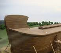
I've been having a go at generating normal maps from greyscale images using nvidias photoshop plugin, it seems to be work ok for my 'blocky metal plate above another blocky metal plate' textures, i've got normal maps made for the ship currently known as the griff_boa 
here's a screen grab of it in rendermonkey using ahrumans normal map enabled shaders:

the lighting looks a bit odd though because (i think) of the weird way i've laid out the UV map
here's a screen grab of it in rendermonkey using ahrumans normal map enabled shaders:
the lighting looks a bit odd though because (i think) of the weird way i've laid out the UV map
-
DaddyHoggy

- Intergalactic Spam Assassin

- Posts: 8515
- Joined: Tue Dec 05, 2006 9:43 pm
- Location: Newbury, UK
- Contact:
No longer can you avoid the title "God of Modelling" - even if you claim to do it all by accident and theft!
More - More!
Oolite Life is now revealed hereSelezen wrote:Apparently I was having a DaddyHoggy moment.
-
Commander McLane
- ---- E L I T E ----
- Posts: 9520
- Joined: Thu Dec 14, 2006 9:08 am
- Location: a Hacker Outpost in a moderately remote area
- Contact:

-
Griff
- Oolite 2 Art Director
- Posts: 2510
- Joined: Fri Jul 14, 2006 12:29 pm
- Location: Probably hugging his Air Fryer
all the cool stuff comes from what the shaders are doing really, i just soak up all the praise
I've uploaded the griff_boa from the screenshot above in an oxp, it only works in the trunk build it yourself oolite that the devs work on behind the scenes, there's no glows or fancy effects in the shaders, just the bump mapping and the griff_boa's simpley float about like asteroids with the dumbAI.plist.
download here: http://www.box.net/shared/5xh41f6466
the normal maps were made using the nvidia photoshop plugin, using the default settings - there were a lot of options i don't know what they mean so i just left them be! Basically the 'height maps' were painted in flat shades of grey with lighter shades of grey being 'higher' than darker shades:

the shaders are a (horribly mangled by me) version of Ahrumans brickwork cube shaders from a few days ago, i took out the parallax map stuff for the moment and tried to fix the mirrored UV's causing the lighting to appear wrong effect by adding this to the vertex shader - please feel free to point and laugh:
completely wrong i should imagine, although the light now appears to come from the correct direction on the mirrored side, i suspect it's been broken across all other parts of the model. I'm desperate not to have to re-UV the model to do away with the overlapped UV's - i have actually re-layed out the UV's over the last few days but i can't muster the enthusiasm to re-work all the textures & heightmaps so they fit the new layout, but the normal mapping stuff is so exciting i probably will knuckle down and do it at some point.
I've uploaded the griff_boa from the screenshot above in an oxp, it only works in the trunk build it yourself oolite that the devs work on behind the scenes, there's no glows or fancy effects in the shaders, just the bump mapping and the griff_boa's simpley float about like asteroids with the dumbAI.plist.
download here: http://www.box.net/shared/5xh41f6466
the normal maps were made using the nvidia photoshop plugin, using the default settings - there were a lot of options i don't know what they mean so i just left them be! Basically the 'height maps' were painted in flat shades of grey with lighter shades of grey being 'higher' than darker shades:
the shaders are a (horribly mangled by me) version of Ahrumans brickwork cube shaders from a few days ago, i took out the parallax map stuff for the moment and tried to fix the mirrored UV's causing the lighting to appear wrong effect by adding this to the vertex shader - please feel free to point and laugh:
Code: Select all
     if (gl_Vertex.x > 0.0)
TBN = mat3(-t, b, n); -
JensAyton
- Grand Admiral Emeritus
- Posts: 6657
- Joined: Sat Apr 02, 2005 2:43 pm
- Location: Sweden
- Contact:
Matrix maths hurts my brain, but that’ll probably work… for faces whose vertices are entirely on one side of the dividing line. It definitely won’t work for anything that crosses the border. To fix that, there are two options:Griff wrote:tried to fix the mirrored UV's causing the lighting to appear wrong effect by adding this to the vertex shader - please feel free to point and laugh:
- Only have flat surface (normal = 0, 0,1) on all faces crossing the mirror plane.
- Do the flipping in the fragment shader.
E-mail: [email protected]
-
Griff
- Oolite 2 Art Director
- Posts: 2510
- Joined: Fri Jul 14, 2006 12:29 pm
- Location: Probably hugging his Air Fryer
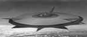
I've bump mapped the griff_coriolis using the same normal maptechnique as the griff_boa ie painting out a greyscale 'height map' and converting it to a normal map using the nvidia photoshop plugin.

edit: Just noticed i'd uploaded a version with a half-rez diffuse map by mistake, i've updated the oxp and tweaked the shader slightly to ramp up the shiny (makes it look a bit more metallic rather than the plasticy look it had earlier):

download here http://www.box.net/shared/ifcaqnxdhf (won't work with the test release versions of oolite, only the build it yourself trunk version)
I haven't bothered with that flip the binormal thing i was so proud of working out earlier in the boa oxp, the lighting works a lot better without it
edit: Just noticed i'd uploaded a version with a half-rez diffuse map by mistake, i've updated the oxp and tweaked the shader slightly to ramp up the shiny (makes it look a bit more metallic rather than the plasticy look it had earlier):
download here http://www.box.net/shared/ifcaqnxdhf (won't work with the test release versions of oolite, only the build it yourself trunk version)
I haven't bothered with that flip the binormal thing i was so proud of working out earlier in the boa oxp, the lighting works a lot better without it
-
DaddyHoggy
- Intergalactic Spam Assassin
- Posts: 8515
- Joined: Tue Dec 05, 2006 9:43 pm
- Location: Newbury, UK
- Contact:
It gorgeous Griff - well done! 
Oolite Life is now revealed hereSelezen wrote:Apparently I was having a DaddyHoggy moment.
-
Pangloss

- ---- E L I T E ----
- Posts: 303
- Joined: Wed Dec 13, 2006 5:57 pm
- Location: Scranton, PA (via Stevenage, Herts)
I think I just cried, that was so beautiful. And if all you need to make the textures look bumpmapped is to alter the level of brightness, it would be really easy to have raised panels on a ship (just select the area to be raised and add some lightness) and even have stark panels meet smoother surfaces by mixing up those sudden changes with gradients of shades of grey. Like a Magic Eye picture, but without the need to go cross eyed.
EDIT: or like a topographical map. Dark area = low, light area = high.
EDIT: or like a topographical map. Dark area = low, light area = high.
"All is for the best in this best of all possible worlds..."
Dr.Pangloss, Voltaire's 'Candide'.

Dr.Pangloss, Voltaire's 'Candide'.
-
JensAyton
- Grand Admiral Emeritus
- Posts: 6657
- Joined: Sat Apr 02, 2005 2:43 pm
- Location: Sweden
- Contact:
Elsewhere, I wrote:
Examples:
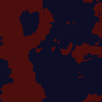
The first uses this texture:
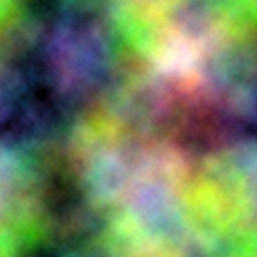
In the second, the green channel is replaced with a basic noise texture:
Obviously this isn’t a finished shader, but you could use it as a diffuse component in a shader instead of a texture (or, more practically, use an alpha channel to mix it with a texture).
A suggested colour scheme for camouflage: blue-black and gl_LightSource[1].specular * 0.2 (i.e., the colour of local sunlight, darkened).
Side note: I tried using the wave() approximation from Freaky Thargoids instead of sin(). There was no significant speed difference on a Radeon HD2600 (less than 1 % in favour of sin()), but probably would be on the earliest GLSL-capable cards.
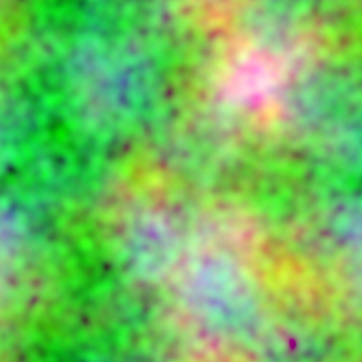
Edit: Greater variation can be achieved by moving the channels around independently, like this:
This requires the noise texture to be a tiling pattern (the ones above are) and use of the repeat_s and repeat_t properties.
Video (MPEG-4, 2.5 MiB)
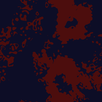
Here’s a basic implementation:Ahruman wrote:Shader idea: a moving-blotch camo texture, along the lines of Rorschach’s mask in Watchmen. Could probably be done along the lines of the Freaky Thargoids shader.Griff wrote:cowprint texture
Code: Select all
uniform sampler2D tex;
uniform float uTime;

const float k2Pi = 6.283185307179586;

const float kTimeRate       = 0.1;
const float kSharpen        = 40.0;
const float kBias           = -2.0;

// 5.0 is the total magnitude of n1..n3 times two.
const float kScaledSharpen  = kSharpen / 5.0;

const vec3 color1 = vec3(0.05, 0.05, 0.15);
const vec3 color2 = vec3(0.3, 0.05, 0.05);


float Noise(vec3 sample)
{
    float n1 = 0.0, n2 = 0.0, n3 = 0.0;
    float time = uTime * kTimeRate;

    n1 = sin(sample.r * k2Pi + time);
    n2 = sin(sample.g * k2Pi * 3.0 + time * 1.003) * 0.5;
     n3 = sin(sample.b * k2Pi + time * 2.0);

    float n = (n1 + n2 + n3);
    n = smoothstep(0.0, 1.0, n * kScaledSharpen + kBias + 0.5);

    return n;
}


void main()
{
    vec3 sample = texture2D(tex, gl_TexCoord[0].st).rgb;

    float n = Noise(sample);
    vec3 diffuseColor = mix(color1, color2, n);

    gl_FragColor = vec4(diffuseColor, 1.0);
}The first uses this texture:
In the second, the green channel is replaced with a basic noise texture:
Obviously this isn’t a finished shader, but you could use it as a diffuse component in a shader instead of a texture (or, more practically, use an alpha channel to mix it with a texture).
A suggested colour scheme for camouflage: blue-black and gl_LightSource[1].specular * 0.2 (i.e., the colour of local sunlight, darkened).
Side note: I tried using the wave() approximation from Freaky Thargoids instead of sin(). There was no significant speed difference on a Radeon HD2600 (less than 1 % in favour of sin()), but probably would be on the earliest GLSL-capable cards.
Edit: Greater variation can be achieved by moving the channels around independently, like this:
Code: Select all
    sample.r = texture2D(tex, gl_TexCoord[0].st + vec2(0.01, 0.005) * uTime).r;
    sample.g = texture2D(tex, gl_TexCoord[0].st + vec2(0.013, -0.02) * uTime).g;
sample.b = texture2D(tex, gl_TexCoord[0].st + vec2(-0.008, 0.017) * uTime).b;Video (MPEG-4, 2.5 MiB)
Last edited by JensAyton on Sun Jan 18, 2009 5:33 pm, edited 1 time in total.
E-mail: [email protected]