
This header posting will be, where the complete tutorial should be in the end.
I already tried to create my own station OXP, read all wiki entries on this I could find and dissected other OXPs to no avail. As I couldn't spawn even one model I couldn't make progress from there on. Even worse: I was unable to find the source of the error. Was it the model, the shipdata.plist entry or did I call the addShips() method wrong? No idea. Looking for something on base of guesses for hours is no fun. It's worse, if success just doesn't come.
This tutorial should include the following steps:
Creation of a simple model (a cube) in Wings3D.(done)Exporting and converting it with the python script.(done)Integrating it into an OXP.(done)Creating a shipdata.plist for it.(done)Spawning it.(done)- How to place it at certain coordinates and to orientate it
(spinning). (just a few simple examples) Adding the standard docking bay of the Coriolis station.Build a own one. (Done)- Understanding how to place flashers (optional)
- Understanding other simple sub-entries. (optional)
It's late now. I'll add the description for the cube and its exportation tomorrow. [wiki]OXP howto model[/wiki] already gives clear answere to this, but a short step-by-step summery can't hurt. I'll write that part myself.
EDIT:
Tutorial:
Welcome to our little orbital and interplanetary space station building workshop. In this tutorial we will go through the most important steps to build a very, very plain station. If you feel, that we might have skip an important step for you or haven't gone into the details of a step deeply enough, feel free to complain in the thread below. Who knows? You might even be heard. But we won't describe here detailed stuff, for example how to create a detailed model. There are lots of tutorials, that do that. This tutorials goal it to help you create your first station.
Setup:
Before we begin make sure you have everything you need:
- We will use Wings 3D as modelling tool. (Offical page)
- We need the script file Obj2DatTex.py (available here) to convert the created model into a dat-file for Oolite to use.
- We also need Python 2.7 for running this script. (Official download page) There might actually be big deferences between the version of Python! The scripts won't run on version 3! So please install a version of 2.7 or at least a version 2. off sort.
- If you haven't already installed it, you really should consider using the OXP Developer release of Oolite (Get it here. (Scroll down. It's there.))
- Wings 3D 1.5.4
- Python 2.7.10
- Obj2DatTex.py of 17 Jul 2012
- Oolite 1.82 OXP Developer release
Alright. We're set. Start up Wings 3D. There should be a grit on grey background. Right click somewhere on the grit and select "Cube". (It should be the first entry in the menu.)
Did a cube appear? It should have. Good. The default cube you just created has a size of 2x2x2 units³. One unit is considered one meter. A 2m x 2m x 2m sized station is a bit small. We change that.
See these four depictions of cubes at the top center of the Wings 3D GUI? Mark the complete red, most right one, to select whole objects, and mark the cube. It should should have turned red now. Right click, click ".Scale Uniform." and hit the tab key. Has a window named "Numeric Input" appeared? You're doing fine so far. Type in "40000.0". That looks excessive, but your station is 2m wide and this will increase its size to 2m x 400 = 800m.
The cube is gone? Use your mousewheel or whatever you use to zoom to zoom out. There it is again.
We're done with the modelling for now. (That was quick, huh?) A cube is a fine example of elite style space architecture and makes a fine station. (IMO at least.) Keep in mind, that all too detailed models might look out of place for an elite universe structure (that much is just personal taste) and slow down the overall performance of the game.
Save your work somewhere were you'll find it again. Name it, well, "Cube".
Exporting the model (to *.obj):
Its time to export your work. Select the cube again and this time select "File" in the top menu bar and hover your mousepointer over "Export". In this menu you'll find the entry "Wavefront (.obj) ...", but you don't want to click that entry directly. There is a small window icon right beside it. Click on that one. In this new window under the entry "Tesselation" select "Triangulation" and press OK. There should be a file named Cube.obj in the same directory as your saved work.
Converting the model (from *.obj to *.dat):
The next part is tricky to describe as it might differ depending on which operation system (os) you are using. But first copy Obj2DatTex.py into the save working directory as the other files.
In most window based os, like Windows, the py-files (python script) are already linked to the python interpreter. Try to drag and drop Cube.obj onto Obj2DatTex.py and look if a file named Cube.dat appeared. If it did, you are done here and may skip to the next section.
If it didn't you now have to use the shell. I'm not going to describe how to open a command shell for every os here. You have to search for that yourself on the net. Use "how to open a command shell window" + your os name in a search engine of you choice.
In the command line of your shell type "python" and press enter. If you see the Python version number right at the beginning and the command prompt changed to ">>>", you are good. Make sure the version number of Python is 2.6 or 2.7 or at least something with a 2.7+ at the beginning. If the version number is wrong you either have installed the wrong version or another version that stole the spotlight. In this case, yet again, search the net to figure out how to call the right one. Exit the prompt with the command "exit()".
In case the "python" command didn't yield the Python prompt, you should read the Python F.A.Q. and, you guessed it, look yourself for an answer on the internet.
Change the prompt directory to the working directory. A quick way to do that in most os is to type "cd" into the prompt, press the spacebar one time, drag'n'drop Cube.obj onto the shell window and delete the characters "Cube.obj" from the command, leaving only the path behind. Press enter. Now type the command "python Obj2DatTex.py Cube.obj", press enter and see the magic happen. There you go: Cube.dat. If the file still doesn't exist, yepp, search the web for "howto use python scripts" or ask the board.
Time to cram everything into an OXP.
OXP impementation:
And again, I'm not going into the details of how to create an OXP, as there are quite sufficient tutorials and descriptions about this.
- List of interesting tutorials and descriptions:
- [wiki]OXP standards[/wiki]
- The All-in-One Guide to OXZ Packaging and Distribution
Open the Oolite game folder and open the "AddOns" folder in it. If it doesn't exist, create it. Within create another Folder called "CubeStation.oxp". Yes, the folders name ends with ".oxp" even though it isn't a file. In the OXP's folder create a text file and rename it to "manifest.plist", no ".txt" or anything else after ".plist"
Fill the file with the following code and modify where needed:
Code: Select all
{
	identifier = "oolite.oxp.***yourSignaturInOneWord***.***titleInOneWord***";
	title = "***a fitting title goes in here***";
	author = "***your name goes here***";
	license = "CC BY-NC-SA 4.0"; //Just a suggestion. The license type is your choice.
	version = "0.1.0"; //As this in going to be a very early version, go with a small version number.
	description = "***A fitting description goes in here***";
	category = "Miscellaneous"; //Miscellaneous fits for most bases OXPs.
	tags = ("Miscellaneous", "Station"); // Fill this other tags if you like.
	required_oolite_version = "1.82";
}Code: Select all
{
	identifier = "oolite.oxp.ocz.cubeStation";
	title = "Cube Station";
	author = "ocz";
	license = "CC BY-NC-SA 4.0";
	version = "0.1.0";
	description = "The Cube Station created in that excellent tutorial, that lead you here. :)";
	category = "Miscellaneous";
	tags = ("Miscellaneous", "Station", "Cube Station");
	required_oolite_version = "1.82";
}Code: Select all
{
    "version" = "1.82";
}Code: Select all
"use strict";
this.name			= "Cube Station Script";
this.author			= "ocz";
this.copyright		= "2015 ocz";
this.licence		= "CC BY-NC-SA 4.0";

this.addStation = function (offset) {
	var stationPosition = player.ship.position;
		//Sets the stations spawning location directly at the players position.

	if (offset) {
			//If an offset vector exists, its values are added to the spawning point.
		stationPosition.x += offset.x;
		stationPosition.y += offset.y;
		stationPosition.z += offset.z;
	}

	var cubeStation = system.addShips("cube_station", 1, stationPosition, 0)[0];
	return cubeStation;
}

this.startUp = function () {
	this.addStation(Vector3D(2000,0,0));
		//Let's add a Cube Station 2000m next to the player's
		//initial position in the Main Station.
}this.license already told you. Licenses are important as they, in our communities case, keep beef away form the board. So you better don't use it as is for your presentation for example without mentioning me. But I take it even further! If you use it as a starting point for your own scripts, seeing how general those lines are, I hereby declare, that you don't have to mention my name and/or don't have to share it alike! Same goes for the other lines of code I provide as written examples (the downloadable files excluded!) in this tutorial, which only spans this threats initial post. (This one here, you're reading right now.)
Now, isn't that nice of me? So, change it to your hearts content!
Next open the "Config" folder and create these two files:
"world-scripts.plist"
Code: Select all
(
	CubeStationScripts.js
)Code: Select all
{
	"cube" = {
		model = "cube.dat";
		name = "Cube";
		scan_class = "CLASS_STATION";
		roles = "cube_station"; // <- Note that system.addShips() refers to roles.
	};
}model = "cube.dat"; in "shipdata.plist"? That refers to the model you have converted. But it still isn't in our OXP, is it? Copy it from your working directory into the "Models" folder aaaaaaand we're done here.I also already created that OXP. In case you are lazy and haven't done what I told you in this tutorial, you are in luck. I spoil you: Cube_Station_0.1.0.oxz
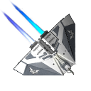
Time for a test drive. Start up oolite, load a game or start a new one and launch from the main station. Somewhere on the radar, there is a new signal. Turn and TADAAAA!!!
'Well....Well...It's... ...pink!', I hear you thinking. But the point is, it's there!
Time to return to the drafting table and finish the stations model. Shall we?
Modelling (part2):
Before you open the model file of the cube again, there are some things we should think about now. We want to finish the model this time and at this point the station is just a pink block in space. So what's missing? A texture and you might want to land on it, so we also have to construct a docking bay, which in turn needs a texture, too. I'll provide both textures, but you have to build the bay. First save these little cartoonish goodies somewhere you'll find them again. They'll do for educational purpose:
Textures:

hull.png by ocz cc by-nc-sa 4.0
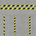
tutorialbay.png by ocz cc by-nc-sa 4.0
Next start up Wings 3D again or close the cube model, if still running in background. We'll need a clean slate.
We'll create a cube again, but this time a bit different. This time it won't be a cube as the sides won't have the same lengths. Right click on the grit again, but this time don't directly click on "Cube" the the small icon right next to it. Give x and z the value 250, but y only 100. This is going to be the landing bay. "Wait!", you might interrupt, ''Are we going to create the bay as different model?" Yupp, you right, but don't worry. It'll be more convenient for future uses. It's best to do it this way right from the start. And in case the model vanished: Did you zoom out far enough?
The side that faces in direction of the z-vector will be the front side. As we want the use the insides as landing bay, select the object and perform the "Invert" operation, you find in the right-click menu. Next up: some texturing.
Under the entry "Window" in the menu bar at the top of the Wings 3D screen you see the subentry "Outliner". Click it. A window appeared. Now deselect the object in the main view, open the right-click menu again and click on "Material...". Name the new material "Dockingbay" in that popup window that followed. And in the next window keep the materials properties how they are and click OK. Now select under "File" in the menu bar "Import Image..." and find "dockingbay.png" you downloaded a few minutes ago. Both "Dockingbay" (the material) and "dockingbay.png" should have appeared in the Outliner window. Drag'n'drop the png in the menu onto the material and chose "Diffuse" as Texture Type. We're set for the "fun" part. Skinning.
Select the whole object again. Do you still remember the four cube pictograms at the middle top of the screen? Select the one, that indicates face selection. (It's the third one.) Right click onto the object and chose ".Material." and then "Dockingbay". Then right click the object again and chose. ".UV Mapping." (It might be hidden under the "More... ->" entry.)
Oh, this is going to be rich.
Another view window called "AutoUV Segmenting" should have poped up. In it's top there are only tree cube depictions. Chose Edge Selection from among them. (It's the middle one.) Now mark every of the twelve edges, right click on one of them and chose "Mark Edges for Cut". Right click again and chose "Continue". And then "Unfolding". You should see a new window with a colorful picture and the faces of the model on it. For one reason or another Wings 3D decided to just create a new material with this texture without asking beforehand, so close that new window. Map the material "Dockingbay" to the object like you did moments ago. Also get rid of that new material "Cube1_auv" and texture "auvBG" from the Outliner window. First the material, than the picture. (Marking, right clicking and "Delete".) And right click that object again and chose ".UV Mapping." to open the Mapping window again, but this time with the right texture.
Press space to deselect everything. I won't tell you how you should map the faces to the texture. Firstly, this would be unnecessarily complicated and secondly this is something you should do by yourself to get the hang of it. Here are some hints though:
- You can select, deselect and move the faces in the mapping window.
- You can see the changes in the main window.
- You can also select and deselect faces by using the main window. Useful the figure out which face is which and to select a certain one, if they overlap in the mapping window.
- They may overlap! Make use of that.
- Right clicking in the mapping window, yields a menu to manipulate the faces.
- Pressing the Tab key while manipulating opens a dialogue to type in numeric values. Useful to turn a face for exacly 90° for example.
- Last, but not least: Make sure to deselect a face, when done with it for now. The space bar is very useful in this hind-side.
You're done? Good. Two more steps and the bay is finished. Remember which face is the front one? That one that lies in the same direction as the z-vector (the blue one) is pointing. That face has to go. Logical, as we want ships to enter the bay. Mark it, right click and chose ".Hole." Done.
If you're asking yourself, why you had to map a side, that was already going to be eliminated, ask that question the people who wrote the converting script. The face is still there in the model. And if the script finds an unmapped face, the texture mapping won't be computed. If the cube or the bay is still pink after mapping, this might be the reason.
And the last step before exporting: Move the bay along the z-vector, so that the 0,0,0-coordinate point lies exacly within the opened side of the bay. You already know enough at this point to do this by yourself, but I still provide the instructions. Select the whole bay, rightclick and select ".Move." Chose "Z" as we are going to move it along the z-axis. Type the tab key immediately!!! (The positioning must be exactly. Undo your actions, in case you screwed up.)
The numeric value window should be open right now. It is calculation time. The coordinate systems center, is in the center of the bay right now. We want it to be that the center of the bays entrance. The bay spans 250 meters along the z-axis. (It's a 250x250x100 box, remember?) From the center of the box to its end it's....?....Right 125m. We have to move it into the negative directory, so the value we seek it: -125. The three x,y and z axis vectors(red, yellow, blue) should now meet in the center of the opening face, if it still would be visible. Save the file as "dockingbay", export the model and convert it much like before with the cube model. Then copy "dockingbay.dat" into the "Models" folder of the OXP.
You might wonder, why you had to move the bay in the end as you did. We have to put both the cube station and the docking bay together. But this won't be happening in a single model. We'll do this later in the shipdata.plist file. For that reason it is good to align the model of the bay in such a way, that it is easier to predict its position, when doing this with numbers alone.
Now open the cube file in Wings 3D and create a material like before. This this use hull.png as texture.Sadly Wrong. I have to change that later. Also you can change the properties of the material a bit. As it's some sort of metal hull, adding a bit shininess to it might look good. Open the right click menu of the material n the Outliner window and chose "Edit Material...". Increase "Specular" a bit and then "Shininess". Play with both values till they are to your liking.
Before you apply that material to the cube, you should prepare the model for creating the entrance of the station. Mark the face that is facing in the same direction, as the z-axis vector is pointing to, as you did with the face of the docking bay you removed later. Don't remove it now. Open the right click menu for it and chose ".Insert." Type the tab key before committing anything. We have to calculate again. The opening of the docking bay is 250m wide and 100m high. The cube's face is 800m high and wide. 25% of 800 are 200, type (100%-25%=) 75%. That should do.
There is now a 200x200 face in the middle. Mark it and open the right click menu again. This time select ".Scale Axis." and chose ".Y." as we want to modify its height. Hit tab again. it's 200m high and we need only 100m. -> 50%.
The width of the face is still incorrect. Of course you could now just ".Scale Axis."->".X." it, but I want you to do something different. Sometimes it's necessary to place vertices precisely. You're going to do that with the four vertices of that face now. Hit the space bar to deselect everything. From the top cube depictions select the first one for vertices adjustments. Mark one of the vertices, open the right click menu, then click "Absolute Commands" and ".Move."
The z value in the window you see now should be 400. Keep that value in mind, as it will be important, when putting the station and the bay together. The x and y values should be -100 or +100 and -50 or +50. The y values are already correct, as the difference between 50 and -50 is 100. The x values must be changed. currently the width of the face is 200 and the values of 100 and -100 mirror that. You need to change the distance between the vertices to 250. So set the values form either -100 to -125 or +100 to +125.
Instead of calculating the values, you could also have opened the bays model again, selected the vertices of the opening individually and wrote the x and y coordinates of them down.
Now apply the hull material onto the cube station. (Of course you don't invert the model this time. Just saying.) When segmenting the models faces for mapping, only mark the twelve outer edges for cutting and keep the front face in one part. Also increase each face's size to fit the whole texture in the UV-mapping window.
The final step of creating this model is to open up the hole for the docking bays entrance. Mark the central face of the front and ".Hole." it. Then export, convert and copy into "Models".
Let's open that shipdata.plist again:
Code: Select all
{
	"cube" = {
		model = "cube.dat";
		name = "Cube Station";
		scan_class = "CLASS_STATION";
		roles = "cube_station";
		smooth = no;
		subentities =
		(
			{
				subentity_key = "cube_docking_bay";
				orientation = (1, 0, 0, 0);
				position = (0, 0, 400);
				is_dock = true;
			}
		);
		rotating = yes;
		station_roll = "0.08";

	};

	"cube_docking_bay" = {
		model = "dockingbay.dat";
		name = "Cube Station Dock";
		smooth = no;
	};

}The orientation shouldn't be of any concern, if you did as I told you, when building the model, as both models are aligned into the direction of the z vector. orientation is interesting, if you want to attach other entities to the station in different angles, like turrets. And that's that on this topic for this tutorial here. If you are interested in this, please look into read [wiki]Quaternions[/wiki] and reverse engineer other OXP's shipdata.plists like of the [wiki]Behemoth[/wiki] OXP for example.
Now the topic on the position entity on the other hand is important for us.
position = (0, 0, 400); shifts the position of the subentity relatively to the main model. As you may have already guessed, the three numbers are the values for shifting them in the three main dimensions x,y and z.In most cases it would be good practise to position the subentities already in Wings 3D at there relatively right position, leaving the entity at a value of
position = (0, 0, 0);, but I didn't do this for a quite good reason: When you will create a spectacular model for your own docking bay, you might want to reuse it for different kind of stations, that come in different sizes. You should consider doing this with every subentry you want to reuse for other projects. If the parts are custom made for each other, for example for a complicated space station with different entities for the stations frame and its hull plating, align them right from the beginning.We aligned the front entry of the bay's model to its 0,0,0-coordinate. The stations entry is not at its 0,0,0-point, but at it's hull. Before I told you to remember the z value of the entrance. It was 400. This makes sense, as the stations form is a cube of 800m per side. And therefore 400 goes at the third position (for the z vector) of the position entity. As the station also rotates now (
rotating = yes; station_roll = "0.08";) it's fairly important that the docking bays position is not shifted across the x or y axis. Imaging you would: In this case the bay wouldn't rotate at the center of the rotation, but around it and that would make docking manoeuvres difficult. When you're done, your OXP should look similar to this one: Cube_Station_0.2.0.oxz
[In-system positioning]
[To be continued]


